
After many diversions and interruptions I have now finalised (more or less) my timing side timing arrangement. I haven't tested it in real life - that will be a while - but have assured myself that the arrangement is easy to read, pretty precise, and what's more important repeatable so I can remove and refit the pointer and it retains its position. Unfortunately both the strobes I have seem to be defunct.
Some pictures:
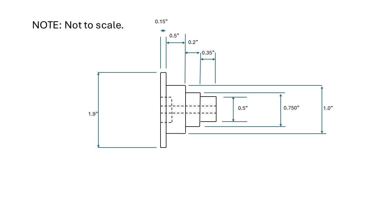
Dimensioned rotor sketch.
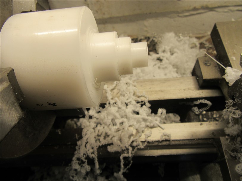
Turning the rotor.
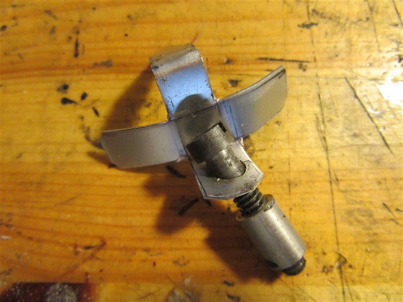
Prototype pointer. Yes the hole is a bit off centre but it doesn't affect anything. The screw goes into the top left timing cover screw hole and the spacer is to ensure the pointer is square.
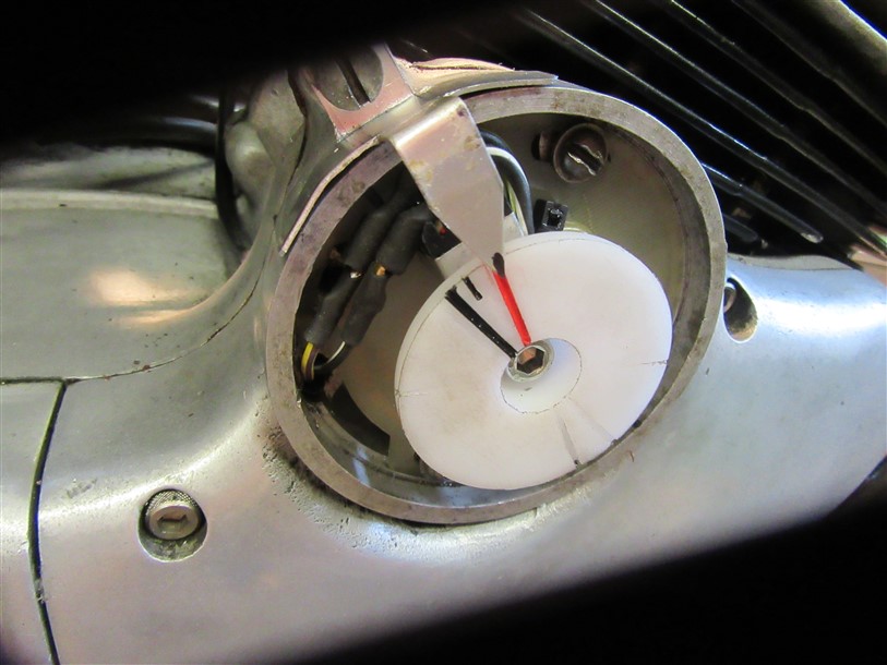
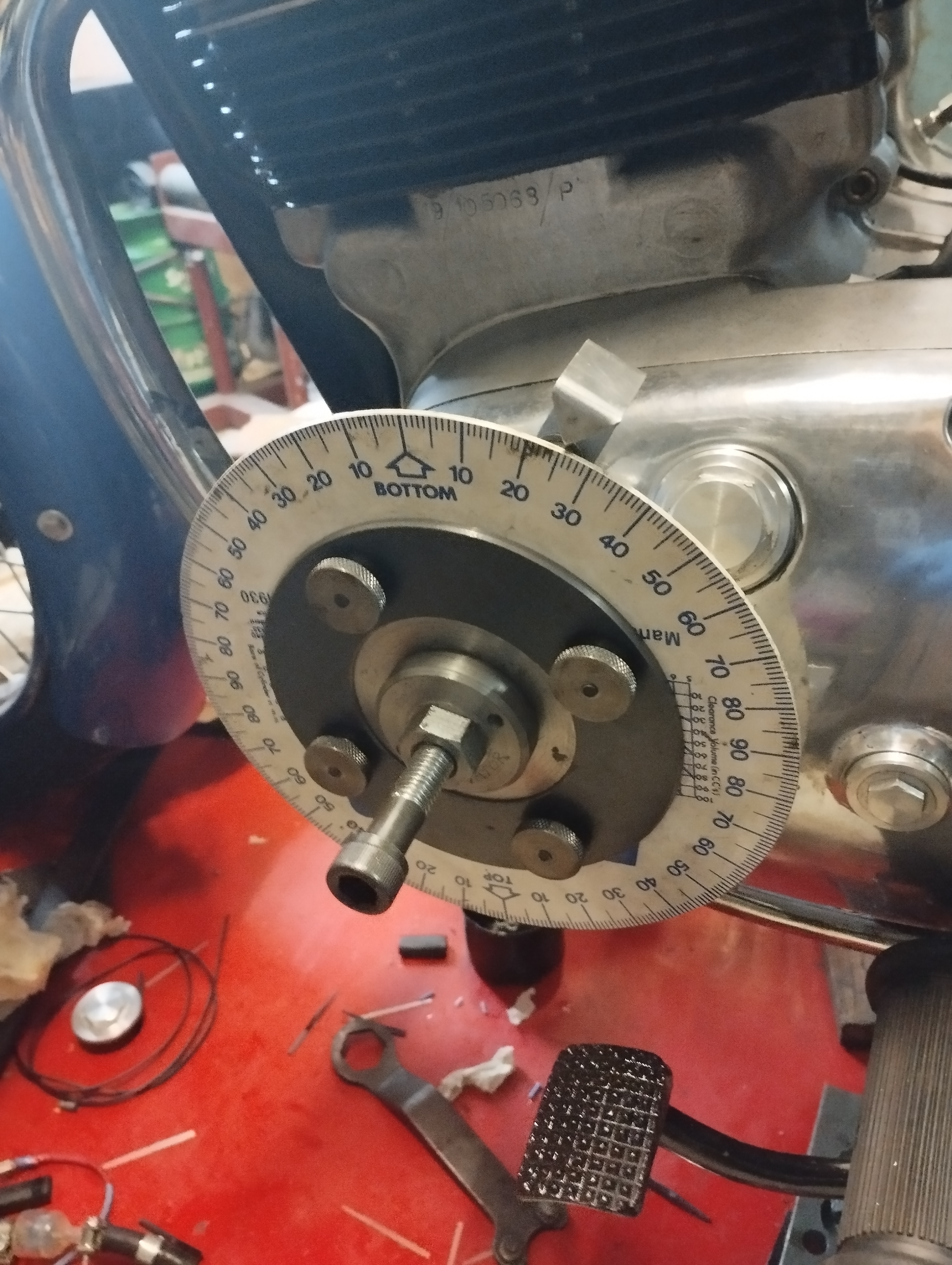
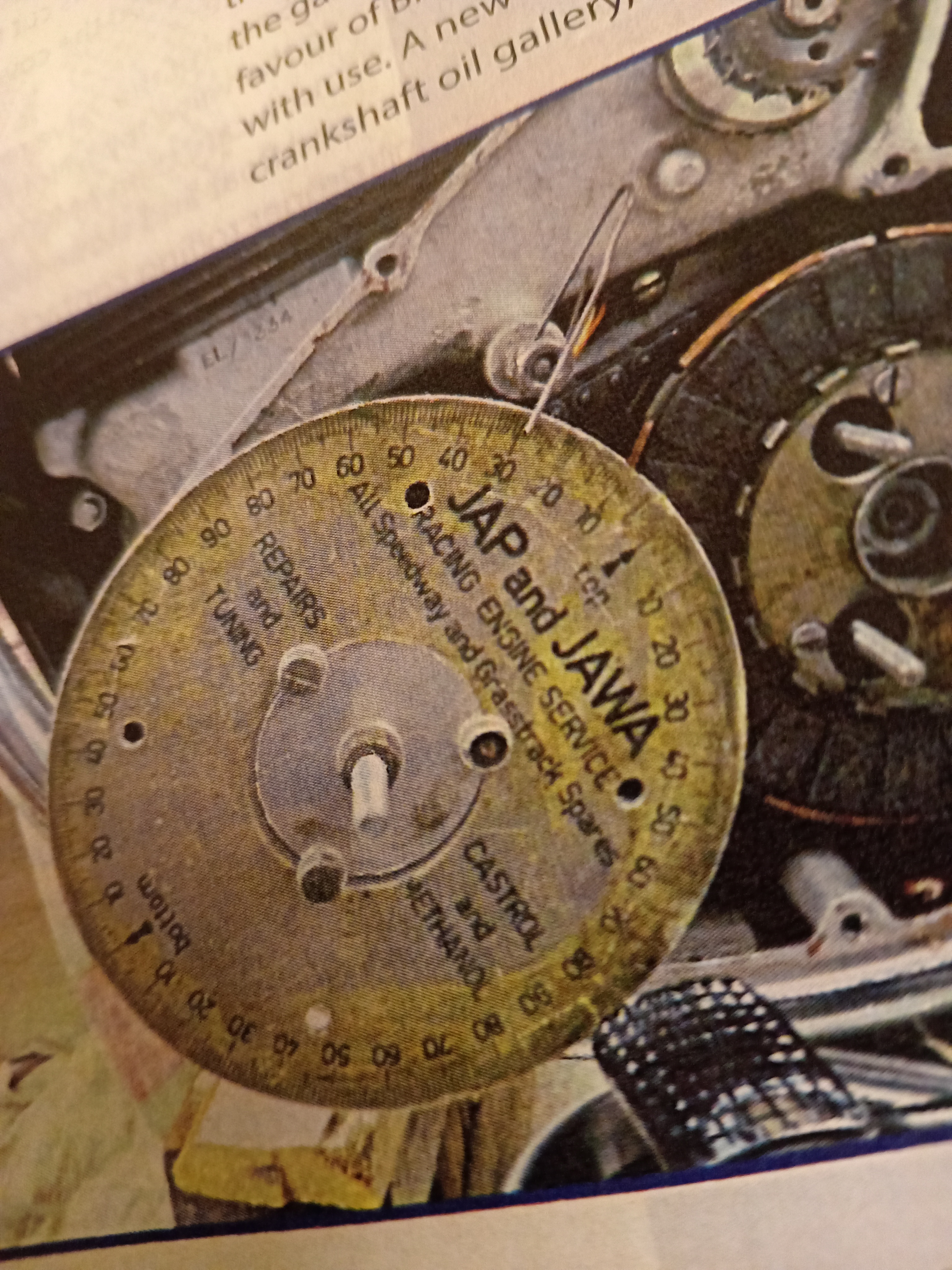
In situ. Note that I'm viewing slightly to one side hence the pointer appears off the timing mark slightly due to parallax. The main black line is TDC; the smaller one is 5 degrees advanced (ie 10 at the crankshaft) and red is 15 degrees ie 30 at crankshaft.
Hi Andrew...
... Yes, the basic rotor would probably be the same although the pointer and fixing would be slightly different but the same general idea. Of course the dimensions of the rotor may be slightly different as the PCB may be different on a Commando.
WARNING: I haven't yet tried this in earnest as I have a number of other jobs to do before I try to start the bike. It's been pointed out that this setup decreases the precision as the rotor is only doing half engine speed but to my mind that will be outweighed by the ease of viewing.
- Log in to post comments
I'd suggest a thinner line…
I'd suggest a thinner line and a sharp pointer, your line must be.a couple of degrees at least!
Dan
- Log in to post comments
I take your point Dan,
but it's very easy to check that the pointer (which is sharp pointed although maybe not clear in the photo) is central in the red or black line. This is of course something of a prototype and I may make an improved version at some time. The lines are a hacksaw blade wide which was the minimum I could get to cut true but I'm sure a better method could be devised.
- Log in to post comments
Idea??
Ian could this setup be adapted for commandos? Question?-as the Commando has a timing 'disc' built in then timing is not hard. And if for any reason you did use this method and the timing chain was a bit slack then your timing would be based on the camshaft position. Timing on the primary side would be timed to the crank shaft.? Is this a good idea?
- Log in to post comments
Yes but -
although the Commando does have a 'built-in' disc, it's still on the opposite side of the bike and thus not that easy I found. My BSA Triple had the alternator (and thus the timing marks) on the same side as the points/EI stator which made timing with a strobe a doddle.
I always used to alter the timing by turning the crank forwards and then back as necessary to ensure that any chain slack was taken into account - seemed to work OK.
- Log in to post comments
You can't do that
I always used to alter the timing by turning the crank forwards and then back as necessary to ensure that any chain slack was taken into account - seemed to work OK...... You can't do that when it is wizing about with a strobe looking at it. So my question still stands, this timing gubbins might work well on the lightweight with gear driven cam drive but located on the cam on a commando?
- Log in to post comments
Accuracy
I have doubts as to whether or not this set up is accurate enough to do the job. Degree lines on the plastic rotor will be, if I've done the maths correctly, will be 0.43mm (0.017") apart at a radius of 25mm.
A fine pen line will be about 0.4 - 0.5mm apart.
Therefore, it will be difficult, if not impossible to see what's happening when its spinning around at speed with a strobe.
How is the plastic rotor located? it needs to run true for accuracy, any wobble will introduce another inaccuracy.
For accuracy it would surely be better to do the job with a decent size timing disc mounted on the crank shaft?
- Log in to post comments
I agree that would be ideal but....
... with the Electra that means dismantling the starter mechanism and undoing the special bolt that holds the ratchet in place. I've already done that and marked the alternator rotor with TDC and 30 degrees before and am using that - hard though it is to see - as the reference for my gadget.
The rotor I've made has a sliding fit 1/4" hole central (bored on the lathe) so should be concentric and consistent. As mentioned I can only try it and see and I will of course report back whether or not it's successful. As it will be very visible it should be possible to see the pointer central in the mark. But if not then I will admit failure. It's only cost me a couple of quid for the acetal material and a few hours of my time.
I know that timing is said to be critical on these bikes with their oversquare dimensions but I doubt very much whether when originally built - and certainly after a few thousand miles - the centrifugal auto advance would be giving anything like the correct timing. I remember that one of the problems with the Commando Combat was its tendency to flop onto full advance at low revs. The workshop manual does not of course mention using a strobe which I accept is necessary for electronic ignition.
I so suspect that a figure slightly retarded from the 30 degrees may in fact suit modern fuels better. I understand that 100 octane (5 star) was originally recommended.
I do welcome all comments positive or negative as there may well be points I've overlooked.
- Log in to post comments
Having owned an Electra, I…
Having owned an Electra, I can say that it is well worth having a go with your method. It is certainly a fairly major job to actually get at the alternator to fit a degree disk.
Also, you should have a very steady strobe flash without any jitter, you are looking directly on the end of the thing causing the 'spark'.
Even with the best of setups, there will always be slight jitter when you are looking at the alternator. On the Commando, the cam chain. On the Electra, the gear train.
- Log in to post comments
Timing disc mod
I like the idea of being able to time from the RH side, the only drawback I see is the fact the disc is at 1/2 speed so needs that little bit more care during strobbing.
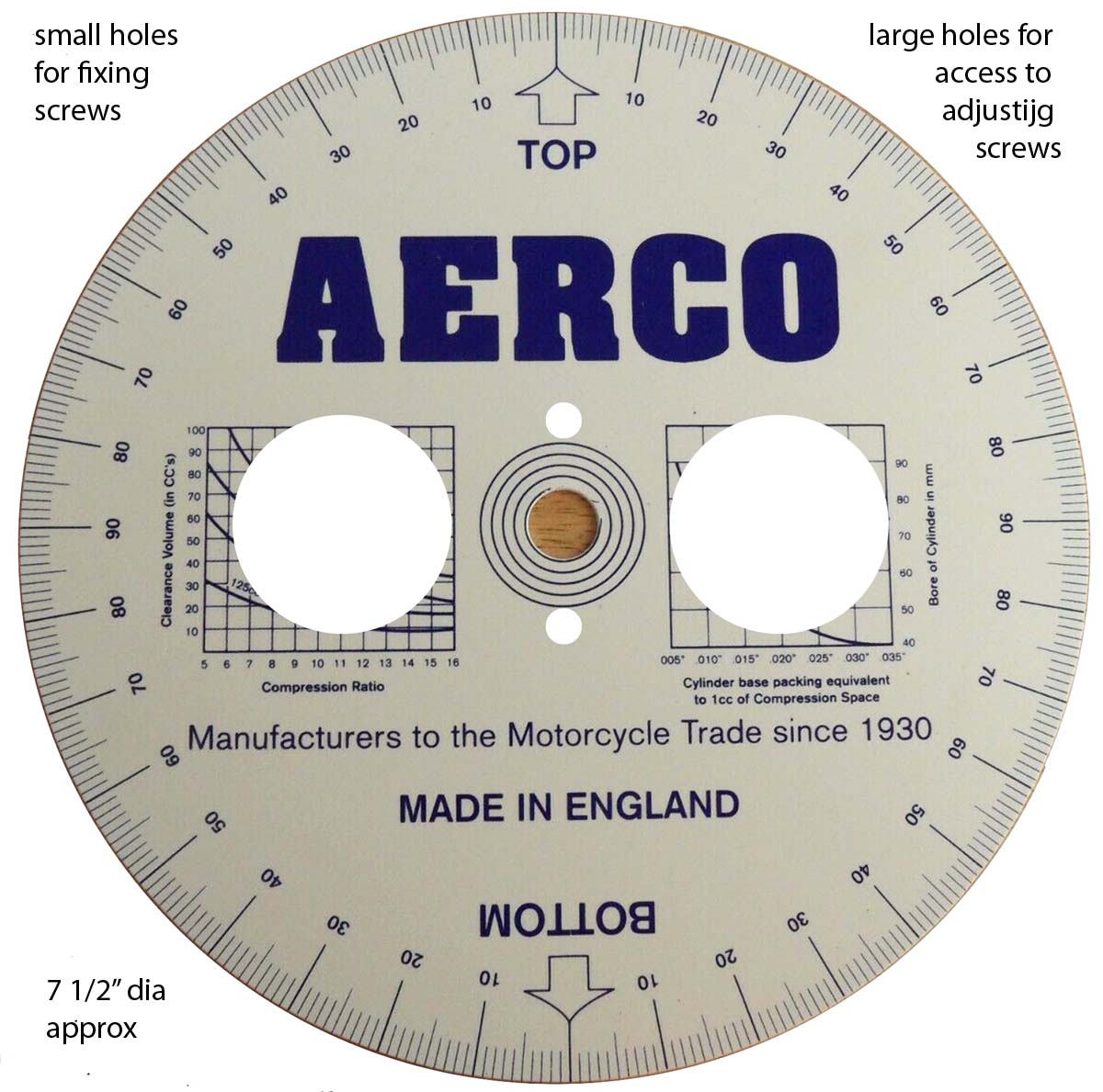
My thoughts are, why not modify a normal timing disc to attach to your rotor adaptor, only needs a couple smallish screws. Also if you cut out apertures you will be able to access the adjusting screws behind the disc. I know you can't use this while the engine is running.
You can still use this to set accurate TDC with the advised piston position tool, I made mine so by adding/subtracting washers it actually stops at 24deg each side, handy for my Navigator but could be any degree you wanted.
More food for thought,
Stan
- Log in to post comments
Accuracy again
I stand by my comments that the OP's setup will not be accurate, far too small in diameter to be of any use. If lines can be engraved on it at 1 degree intervals, they will be too close together to resolve accurately at speed. To put this in to context, look at the 1/64" lines on a steel rule, best looked at, with older eyes, under a magnifying glass, and that's with it not moving, let alone spinning around at 3000+ rpm. Also, being plastic, it will never be consistent in attachment.
Sorry fo being so critical. I don't like doing that without offering a viable alternative. So, here goes.
The use of a large diameter timing discs is an absolute necessity for accuracy. Why not attach the disc to the timing cover with the two screws that fix the points cover. There is, what looks like a machined surface that could be used for accurate location. A carefully machined metal adaptor between disc and cover. The centre of the disc can be cut away to get at the stator for adjusting.
Then make an extended bolt to hold the rotor. The extended end of the bolt could then carry a pointer. This should be made in such away that its (radial) position is adjustable to help with the accurate finding of TDC.
How does that sound? Disc stationary and pointer spinning might fly in the face of convention but will work. It's a way I've seen described in a Ducati manual.
Since this idea of timing (strobing) from the timing side of the Electra engine was first proposed because of difficulties in attaching a timing disc the the crank shaft I've been able to to have a look at some of the starter components. I think it should be possible to do this without removing the starter mech. Modification would be needed to the parts, nothing drastic though. The stationary disc, revolving pointer may well be the way forward here.
The big advantage of timing from the timing side is the need to disturb an oil tight joint is eliminated. To this end I modified a badly corroded and cracked primary chain case cover to get access to the end of the crank shaft (and clutch adjustment). Sealed with a threaded plug and O-ring. I had two reasons for doing this, one being for accurate ignition timing.
Sorry for the long post.
- Log in to post comments
Many thanks again.
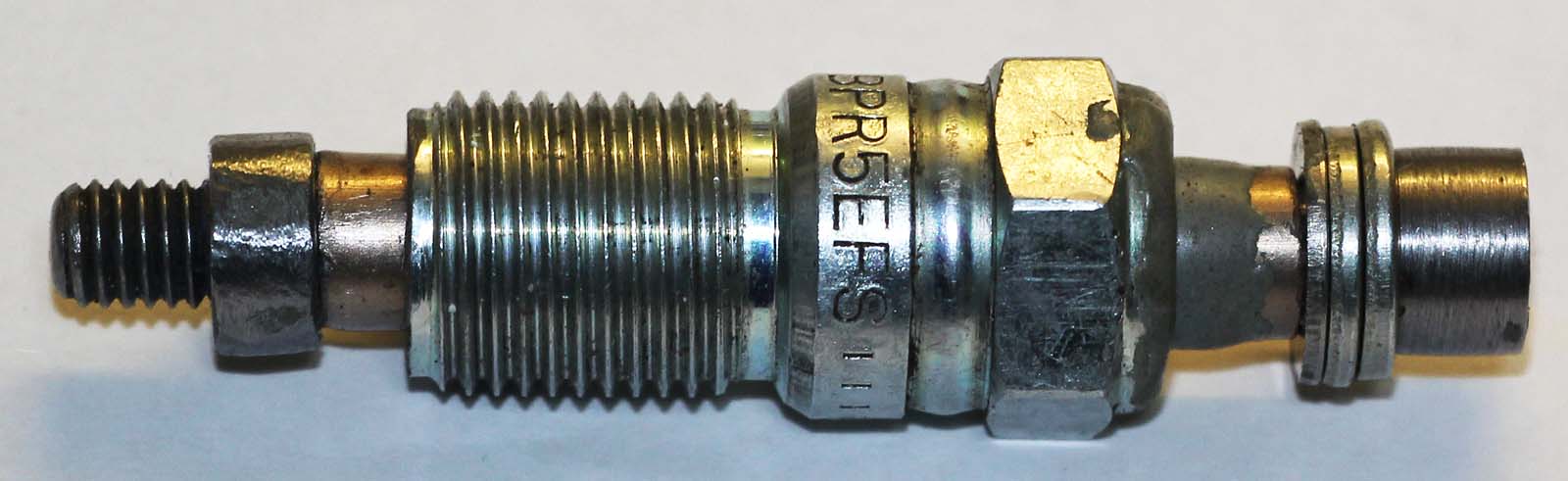
Stan: Good idea re the adjustable piston stop. In fact will be easy for me to modify my existing one as I've tapped the inside of the plug body (3/8 Cycle IIRC) so only need an appropriate length of stud and a locknut. Unfortunately will have to dismantle (again!) the starter which in itself isn't a problem but I've fitted the special ratchet nut with loctite hoping not to have needed it off again. One point: I've drilled a through hole through the central stud of my piston stopper to release compression.
John: Again much food for thought. I do take the point re precision but believe it can't be much worse than aiming at the tiny gap behind the starter mechanism (see pic below). The rotor is made of acetal, a well used engineering plastic. I've secured it using a longer centre screw and the rotor sits on top of the Boyer magnet rotor and it seems robust enough. The idea is that it remains in place so once calibrated should be consistent.
I was considering using the machined surface you refer to to attach the pointer by drilling & tapping a couple of 4BA holes but the face isn't as wide as the photo makes it seem so didn't think it would be robust enough. I'll possibly remake the pointer component out of something a bit stouter than the 1mm alloy although I can remove and replace the current one without losing position. Your idea of attaching the pointer to the rotor and having the timing marks somehow on the rim of the housing could work - I could use the existing rotor and attach a pointer (removable but indexed so as to fit the cover) and maybe just etch some lines on the rim as appropriate. That may be version 2.0!
Sadly there is no way to attach a timing disc to the drive side with the starter in place as the mechanism completely covers the end of the crank / alternator rotor.
I think as well as not having to remove the primary cover (which is off anyway) a significant advantage is being able to operate throttle and strobe from the same side as well as adjusting the PCB position on the fly and without enlisting the aid of possibly inept other household members!
Keep 'em coming!

- Log in to post comments
Incidentally...
... have just worked out the equivalent of 1 degree at the rotor circumference - .0083" (1.9 *3.142/720 - as it's half engine speed) Small but generally easily visible especially when you're not trying to see it through a tiny gap. A difference of 8 thou between two gaps eg points is pretty obvious.
- Log in to post comments
Reading
8 thou easy to see? You must have fantastic eyesight! How are you going to mark the disc? That's some very fine lines to create to be able to differentiate between degrees. That, I think, will be near impossible to do on plastic, steel or aluminium for the rotor would have been a much better choice of material. The static pointer will need to be very fine to pick up each division.
How are you going to use it to find TDC with your set up?
If you are prepared to remove the cover, I can see a couple of ways of attaching a disc to the crank without disturbing the starter mech. Would require some modification to the existing parts but very doable.
- Log in to post comments
You mean like this. Which I…
You mean like this. Which I posted a month ago on a similar lightweight thread. Not theoretical. Made ten years ago and used on other Electras too. No need to undo the crank end bolt.
The Pazon pcb is finely graduated to give you a guide for minor timing changes.
Peter
- Log in to post comments
Not quite like that...
Peter, what I had in mind was to drill a hole through part No. 24752 (from GA drawing). This hole would be as large as possible, 1/2"?
This would give space to fit an extended bolt (24759) or a bolt with a threaded internal bore. This, I think, would be okay for a pointer or timing disc without the need to dismantle the starter mechanism. My approach to this job would to be to make the part(s) from scratch, if possible, rather than modify, just in case something went wrong!
This means removing the cover to set or check the ignition timing, something the OP wants to, in my view, quite rightly avoid if at all possible. My approach would be to create access through the cover, a welded boss and threaded plug. May depended on the availability of an unmolested cover.
Changing the subject, slightly, my interest in Electra's has been piqued by a friend who has an Electra engine minus the starter. Just the primary chain case and the casting that supports the the starter sprocket/ratchet. We have looked into using modern tech to replace the original parts (if they were there!). When this project might happen, no idea. He's happy with kick starting, but who knows what the future might need?
- Log in to post comments
Interesting suggestsion.
24759 is, according to my parts list, the special bolt securing the ratchet to the crankshaft. Part 24752 sprocket shaft is stationary and completely blocks access to the crankshaft. It's only 1/2" or so diameter at its narrowest point and drilling it would weaken it too much I feel.
I have in fact modified a spare crankshaft bolt much as you describe for the initial setting up and marking the crankshaft rotor at TDC and 30 degrees advance using the piston stop and degree wheel method as described by many people.
- Log in to post comments
in the olden days
This topic has been very entertaining. When I got my driving licence and could only afford basic transport ( first car a triumph herald ) I had to learn how to maintain high mileage cars.In those days I always carried a spanner in the glove box which I used to adjust the distributor.
I learnt how to interpret the state of tune of my vehicle through listening and the "feel" of the engine.No strobe available. This along with points adjustment was an ongoing service requirement.
Over the years I have converted all my twin cylinder bikes to electronic ignition.
I hope Ian's timing side method works. Even if he is half a degree out, will it really matter?
- Log in to post comments
Thanks Andrew...
... I also wonder about that and like you kept various rattletraps on the road long past their design life. It'll be a while before I can attempt to start the bike but we'll see. I also believe that the fuel used may have a big effect. A contemporary road test (of the Navi I believe) stated that they used 100 octane fuel which of course is higher octane rating than even E5 at 97. I suspect that an advance figure of 28 degrees may suit E5 better. And as I've mentioned before, even if I'm a degree or two out - and I plan to err on the side of less than more advance - it's going to be far better than how it left the factory.
I do believe that to apply modern standards to a 60 year old design may be gilding the lily!
- Log in to post comments


Ian could this setup be adapted for commandos? Would make setting the timing a one person exercise.