
Can anyone please advise me whether the MCR1 voltage control box should be mounted under the saddle ( how is it attached?) or on top of the toolbox please, for my 1937 16h civilian model
Thanks,
Gary.
Norton CVCs
- Log in to post comments
Thanks Richard, would that…
Thanks Richard, would that be roughly opposite the toolbox or higher up please?
Thanks
Gary.
- Log in to post comments
Location
My only source is the 1937 brochure illustrations. It's a little odd, as from the time that the voltage control system was first trialled by the War Office, all official photos show it above the toolbox. It's not the most convenient location as the toolbox has to be removed to even loosen the clip that allows cable removal. However, brochures from 1938 onwards show that Norton decided on the tool box side. The brochure illustrations for 1937 appear to be an artist's impression. I'm pretty sure that we're seeing the old 3rd brush dynamo and there is no box visible on views from the other side...
- Log in to post comments
The vintagenorton website…
The vintagenorton website has a very good side on factory image of a 1937 16H. Difficult to find...it's under the "older posts" in the "saddle tank 16H" section. It's near the bottom of the page if you copy the link below. As Richard says, the factory brochure doesn't show it on the stay above the toolbox. Good luck if you need to find the correct box. Mine came with a standard box fitted to angle cleats onto the toolbox brackets.
http://www.vintagenorton.com/search/label/Model%2016H%20Saddle%20Tank?updated-max=2015-01-30T22:16:00%2B01:00&max-results=20&start=12&by-date=false
( to look at the image in more detail, you can 'copy image' and paste it into MS Paint)
- Log in to post comments
Did they ever ?
'COV' was a January 1937 series...Was there actually any production with the CVC on the 'drive-side' or was it simply pre-production airbrush work for the catalogue, prior to the details being finalised ?
Over the toolbox seems 'right' to me, but all the left side views in the 1937 literature (they're on Vintage Norton too) show it next to the battery.
It's not actually that difficult to convert the boxes with side-feet used by lesser makes. The feet can be ground off and two 'vees' cut in the base...and a small 'L' bracket soldered on to the rear edge. The female eyes are already formed underneath. The clip shown is a late reinforced type, but it only needs to be sheet steel with two hooks and two holes. 

- Log in to post comments
Thanks Richard. Looks like…
Thanks Richard. Looks like another (unnecessary?) winter task...just to make the wiring less accessible! My bike is from later in 37 (June I think). Obviously I have no idea why or where it lost its original box...or even where the box originally sat.
- Log in to post comments
The Unnecessariness of Rivet-Counting.
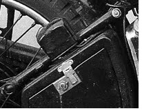
At least David, on a civilian bike (unless someone paid a lot extra), you don't have to worry about them being rated for Ni-Fe or Lead-Acid batteries and marked accordingly. It's almost impossible to read, but this is an 11 9 (November 1939) cover on my December '39 16H. 
- Log in to post comments
All models seem to have used the frame clamp system...I've edited this post as it seems that 1937 (first year with voltage control) had the box on the drive side saddle stay. For 1938 it moved to a location above the toolbox - but still a clamp system.