I think Al Osborn or Grant Tiller may be best placed to comment, if they are around at the moment.
Although it doesn't appear to have caused any obvious problem over several thousand miles, I've become concerned about the axial displacement of my alternator stator and rotor.
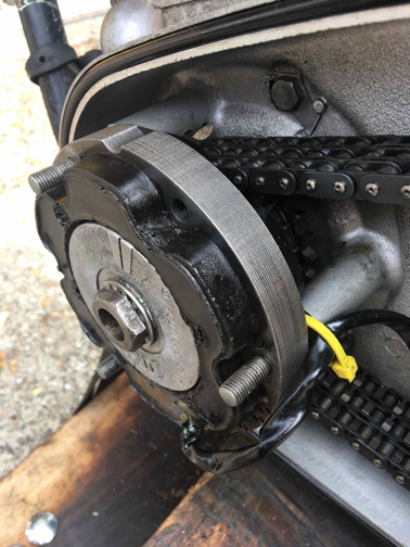
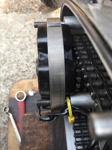
I'm aware that the precise relationship is not critical, but I find it hard to believe that the displacement shown in the following pictures is a good idea.
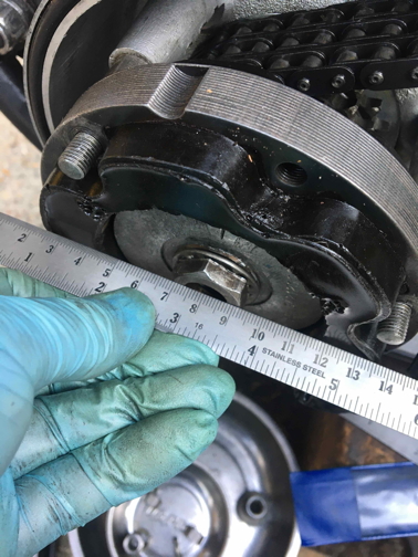
A straight edge across the outer face of the stator just contacts the face of the rotor nut.
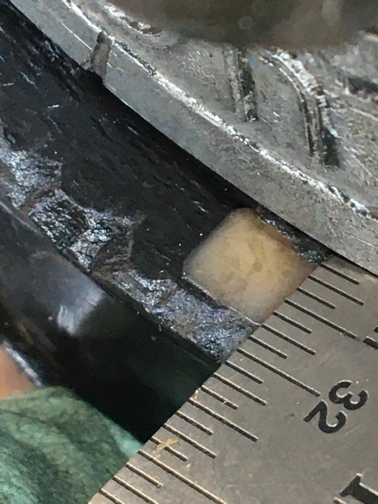
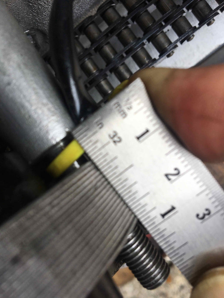
Here we see measurement of the outer face of the rotor relative to the stator.
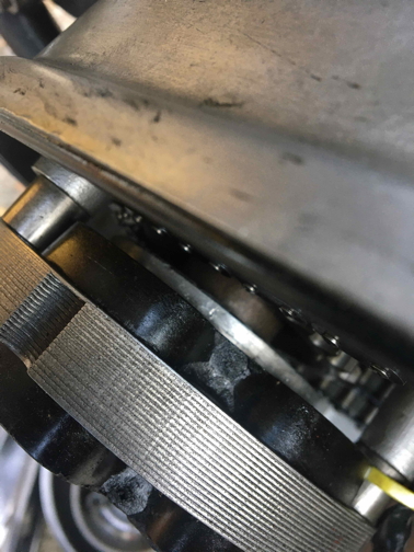
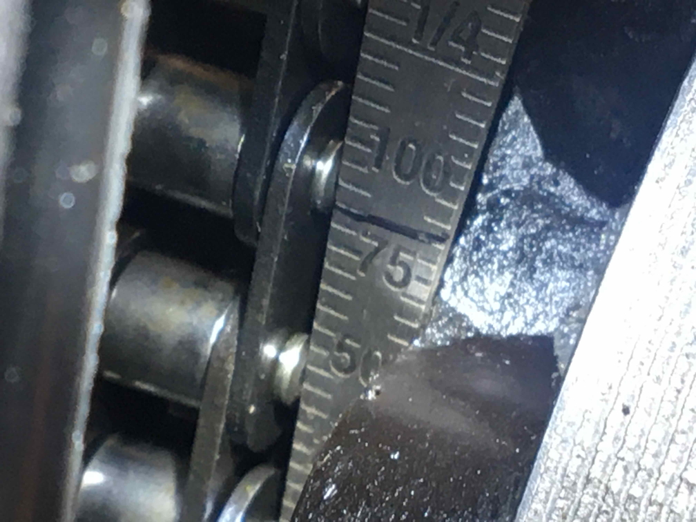
This shows the rotor relative to the inner edge of the stator.
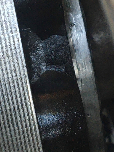
Finally, a close-up version of the previous view.
All my Dommies over the…
- Log in to post comments
If it's not a problem, then…
If it's not a problem, then not fixing it might be a valid course of action.
- Log in to post comments
A new rotor and stator on my…
A new rotor and stator on my 99 needed a spacer behind the rotor to make it look right .
- Log in to post comments
I meant to add: If one…
I meant to add:
- If one searches the AN website for "rotor spacer" a variety of alternative parts come up, which raises the possibility that some p/o has installed a rogue part. The correct one for my bike is 06.0402, which is 0.57 inches deep, according to the AN tech support people. I haven't yet had a chance to measure mine. (I also sent AN the first and last of the pictures in my original post, which they didn't appear to find alarming.)
- If I let the rotor's magnetism set its location on the shaft it settles symmetrically with the stator. I suppose this is not surprising in itself, but in that position it fouls the timing indicator in the outer chaincase. The consequent need to set the rotor asymmetrically in the stator I do find surprising. There seems to be more than enough clearance between the rear of the stator and the primary chain to permit the use of less deep spacers on the mounting studs. Mine are 1/2" deep; I haven't checked this with AN, but their proportions appear the same as the one illustrated on the AN website.
- Log in to post comments
is the rotor narrower than…
is the rotor narrower than standard?
- Log in to post comments
In your photo 3 you can see…
In your photo 3 you can see the encapsulation of the stator is just clear of the alloy stator mounting posts. The difference between the various stators potting compound and its shapes probably was the reason for mounting the stator further out, so there was no chance of an interference with what ever stator was used. If the potting compound will allow it (clear of the alloy posts) you can fit shorter spacers to bring it level. Make sure there is enough chain clearance, Its better to shorten the mounting spacers than to space the rotor outwards.
The new 3 phase stators available have the potting compound very close to the mounting bolt holes, In my Mk3 I had to machine the stator mounting plate (around the bolt bosses) so the stator could fit it. (photos attached)
- Log in to post comments
Some facts
Coaxial alignment is crucial ie if the gap between rotor and stator is less than 8 thou (all the way round) then they can touch/over heat-this mean destruction of the stator and even seizure. IF you are lucky you could have a seized motor at SPEED!!! Do NOT do it.
The alignment in/out is NOT crucial for safety purposes, but it will slightly affect your electricity generated. I have no figures of how many Amps you might loose if you are more than 1/2" out, but as the magnetism in the rotor dictates this anyway, and have you got full magnetism?? This all becomes a bit academic?
- Log in to post comments
Perfectly normal for the…
Perfectly normal for the rotor to be recessed, although your looks a little extreme.
There are spacers 06.0377 that stand the stator off from the inner primary case
You can reduce the length of these a little to bring the stator in board a little - just keep an eye on the primary chain clearance.
In addition, there is a spacer 06.0402 and shims 06.0664 and 06.0665 that sit behind the rotor to stand it out.
Aftermarket stators tend to be a bit thicker with the resin encapsulate which always makes the problem look worse.
Also, the higher output stators are thicker too.
I've done a few of these and only see a negligible drop in charging performance based on the axial alignment of the rotor to the stator.
Unrelated, but perhaps of interest - I always turn down the outside diameter of the rotor on new rotor/stator pairings because I don't find the air gap on the new ones to be sufficient. Again, I observe no drop in charging performance when I do this.
- Log in to post comments
All good stuff Grant.
All good facts Grant, but your last comment 'I observe no drop in charge performance' is not quite right wording. Charge Performance is what goes into the battery and is very dependant on the battery charge state at the time.
Any/all misalignment of the rotor axialy will have the same effect as a slight rotor skim. IE you have increased the gap between the rotor and stator you reduce the amount of electricity quantity-amps PRODUCED. This can/needs to be measured separate to charging the battery.
- Log in to post comments
I have bench tested an RM21 …
I have bench tested an RM21 (LU47205) and a high output RM24 (LU47244) with no load, a 1 ohm 50 watt load and a 1 ohm 100 watt load at 3,000 rpm (the most my 1hp myford motor would do safely) and I measured the output with my Avo before and after skimming a brand new rotor (I always aim for a 12 thou air gap).
On the basis I saw no discernable difference in output, I am more than comfortable recommending the same to others.
On two electric start Commando engines (a 750 with a cNw electric start kit and a 850 MK3 with an uprated 4 coil/4 brush Prestolite), both alternators charge their oversized AGM batteries via Shindengen SH775 open-type regulator rectifiers and show a decent 13 volts within just a few minutes into a ride after a cold start.
Agreed nothing scientific and no specialist test equipment, but good enough for me.
- Log in to post comments
Many thanks to all who have…
Many thanks to all who have responded, but especially to
- Grant Tiller and Peter Shand for encouraging me to pursue the idea of shorter stator spacers; measurement suggests that substituting 1/4" versions for the existing 1/2" ones would still leave over 1/16" clearance with the pins of the primary chain (spacer to potting clearance permitting). Naturally I'll remeasure very carefully before proceeding and again after installation.
- Al Osborn for Grant for their wise reminders about the importance of adequate radial clearance — always worth attaching to any correspondence about this area!
- Log in to post comments
Rotor to stator clearance
At the risk of hijacking this thread, I am intrigued as to why its considered necessary to increase the clearance between rotor and stator? 8 thou all round is plenty to ensure mechanical safety, surely? Why could this clearance close up?
In my latest efforts in fitting a Lucas alternator I started by postioning the stator as close as safely possible to the primary chain. I did this to reduce overhang of the rotor from the main. Then lined up the stator laminations with the rotor magnets (axially) and made a spacer of appropriate thickness.
- Log in to post comments
crank shaft?
Crank shaft run out?
- Log in to post comments
If runout is feared (which…
If runout is feared (which presumably might be an issue with rotors as well as cranks), does this not suggest that measuring rotor/stator clearance should be done at several crank positions?
I have no idea what degree of runout might be expected with properly-assembled correct parts, but say it is 0.002". If one sets the stator at 0.008" symmetrically at some given crank position, then at 180° from that there will be some point where the clearance is now 0.004".
- Log in to post comments
It's not crank runout, its…
It's not crank runout, its the fact that the crank 'whips' (bends) at high revs and will cause the rotor to rub on the stator. 8 thou minimum clearance, the greater the better. That is also the reason that getting the rotor as close to the sprocket as possible is better as it reduces the 'whip' effect.
- Log in to post comments
Rotor clearance
My view on the specified clearance is that it was done so the generator could be assembled, during production, on any engine without risk of interference. That is to say tolerance build up was checked on all the components involved with the generator mounting, then diameters of rotor and stator bore were decide on so that they will never touch.
If the clearance is found to be at fault then its highly likely that the parts relating to the mounting rather than the generator are at fault and should be thoroughly investigated. Reducing the diameter of the rotor is not the way to correct clearance errors.
- Log in to post comments
Julian, No problem at all…
Julian,
No problem at all doing that especially with a new build or new parts, or being suspected having stripped and existing system. The sum of the tolerances could certainly work against the 0.008'' gap. There are an awful lot of tolerances from the crank centre to the rotor and stator mounting that need to be considered.
- Log in to post comments
I suspect that temperature…
I suspect that temperature comes into the equation.
When you consider the heat generated from both the current generated through the alternator coupled with the engine combustion heat transferred through the crankshaft especially at sustained high RPM.
Think of the tappet clearance of .008" for the exhaust valve similar gap.
- Log in to post comments
An update
I adopted the reverse of my earlier tactic by removing the spacers and allowing the stator to align itself to the rotor.
As the pictures show, this proved to be pretty much the equivalent of using 1/4" spacers. There was some evidence that the stator was very slightly impeded by contact between the potting and the aluminium pillars of the inner chaincase, but this should be easily dealt with by minor easing.
It was quite difficult to get a clear measurement of the clearance between the alternator potting and the chain (I resorted to a bore gauge), but it appears to be more than adequate.
- Log in to post comments
better fit
that looks like a good move, inwards!
- Log in to post comments
Some interesting thoughts on rotor clearance
Pleased to see the OP has got the problem sorted.
As has been mentioned checking the gap in several positions is a good idea.
One thing I will take issue with is that heat has something to do with the wide clearance. While things will heat up a bit it will get nowhere near hot enough to have any effect on clearance. If things got that hot the main bearings would fall out the crank case!
Can't say I have ever noticed any dimensional changes between old and new Lucas rotors (except the bore) and stators. If the mounting for them is concentric then no problem. Eccentricity in the mounts needs investigating and correcting.
Incidentally, the only mention of checking rotor to stator clearance in a workshop manual I have found, are alternator equipped Royal Enfield's. Anymore?
- Log in to post comments
Having had one....
Having had one alternator seize due to failing to take heed of the 8 thou. I do not take chances.
The 8 thou I quote came from a Lucas agent who sold the alternators and supplied me for trade with the alternators.
- Log in to post comments
On my T140, I found the…
On my T140, I found the stator was very tight on the studs, such that the stator was hard to fit and movement to centralise the rotor was impossible. The studs were not bent at all. I ran a drill bit down the stator holes and found that one hole was pretty much clear already, but two were tight and material was removed when the bit was part way through the pack of plates, as if some of the plates were slightly misaligned. Odd, because I would have thought the holes would have been drilled after the stator was assembled and the stator plates solidly located. Whatever, after using the bit, the stator slid smoothly down the studs and there was now slight movement to allow an even air gap to be set.
- Log in to post comments
Sounds good but.....
Sounds good to sort this BUT, IF you succumb to any movement on the stator by way of stud holes to get concentricity 8 thou gap etc then the stator can then move back and 8 thou is lost-disaster awaits.
- Log in to post comments
As soon as I....
..... hit post I knew someone would find references to checking rotor to stator clearances elsewhere! Turning down the rotor really is a classic case of symptomatic treatment. The cause needs to be investigated and corrected as spelt out in the workshop manual. Although how one realigns the studs I'm not sure. Also, this sort of work could be storing up trouble for future owners of the bike.
- Log in to post comments
John, the cause is simply…
John, the cause is simply that the tolerance on the modern components ‘vs’ the original is very different.
The original spec of the Lucas Rotor and Stator was for an outside diameter of 74mm on the rotor, and an inside diameter of 75mm for the stator (those numbers were given to me by LAP a few years back)
1/2 a millimetre is just over 19 thou.
I have never seen the gap to be that extreme on the older OE components - the protruding stamped out laminates of the stator frame are always closer to the rotor than that.
But not the 5 thou I see on brand new Lucas (Wassell) kit fresh out of the box
I personally seek out a 12 thou air gap, as I believe there is crank flex when you snap shut the throttle from WOT. Just my opinion of course, and what I choose to do on bikes I work on.
- Log in to post comments
John, just for sake of…
John, just for sake of completeness, here is an excerpt from the Triumph factory workshop manual seeking a similar setup to Norton.
- Log in to post comments
If I had..
...oodles of money, no expense spared, I'd reconfigure the timing side to incorporate the alternator. Triumph did this on the Meriden Tridents. Seems a much more sensible idea to me- no whip on the crankshaft end, which must occur on the drive side due to sudden torque variations during hard acceleration/ gear changes/ deceleration. Then, whilst I was at it, get rid of the chain drive to the camshaft, with all it's inherent foibles affecting valve timing, and also ignition timing for the later points-in-the-side engines. Oh and then a bit more space on the drive side for a sturdier starter drive arrangement. Well a chap can dream can't he....
- Log in to post comments


All my Dommies over the years the rotor and stator were pretty much level. Can't comment on commandos, but it looks to me like a miss match of parts somewhere along the way?