
As we all know, timing the lightweights using markings on the alternator rotor and a pointer on the stator is the usual method advised. It's especially tricky on the Electra with the starter mechanism obscuring the relevant parts, and in any case needs the primary cover to be removed and the engine run with consequent flailing chains and oil everywhere.
A post on the facebook light twins page gave me cause for thought. Boyer an Pazon are both set up by setting the engine on full advance and lining up the magnet with an appropriate hole in the PCB.
My thought is that if I paint the magnet heads a suitable bright colour, I should be able to check the timing using this and a stroboscope. I should be able to see the magnet through the hole, and it should approach and reach centrality as the revs rise.
Any thoughts?
If you can accurately mark…
- Log in to post comments
Strobing ignition
Ian,
The way I see it you need two accurate non adjustable points to check the ignition with a strobe. A fixed static pointer secured relative to the engine case and an accurate revolving timing mark relative to the crankshaft degree showing the required ignition full advance. But this is what you are trying to avoid.
Your idea uses two variable points. First, the rotor which isn't/can't be positioned at any accurate position, rather it is roughly set on installation. Second is the variable plate which is in effect the means of adjusting the correct firing point for the spark. You have no accurate datum to strobe and measure the ignition point.
I understand your thoughts but to me it can't work for my reasons above. Hope this helps. Stan
- Log in to post comments
Timing an Electra
Ian,
The timing procedure for Jubilee and Navigator with points is well described in the Norton Twins manual issued by AMC.
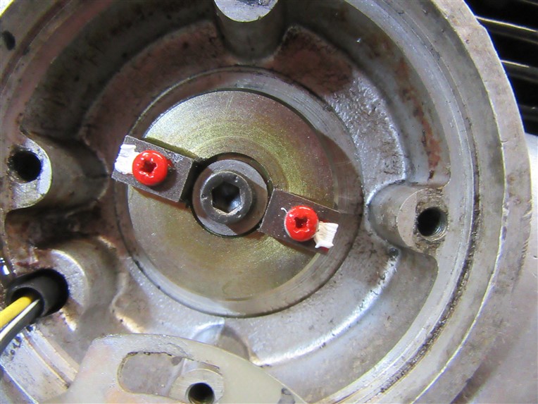
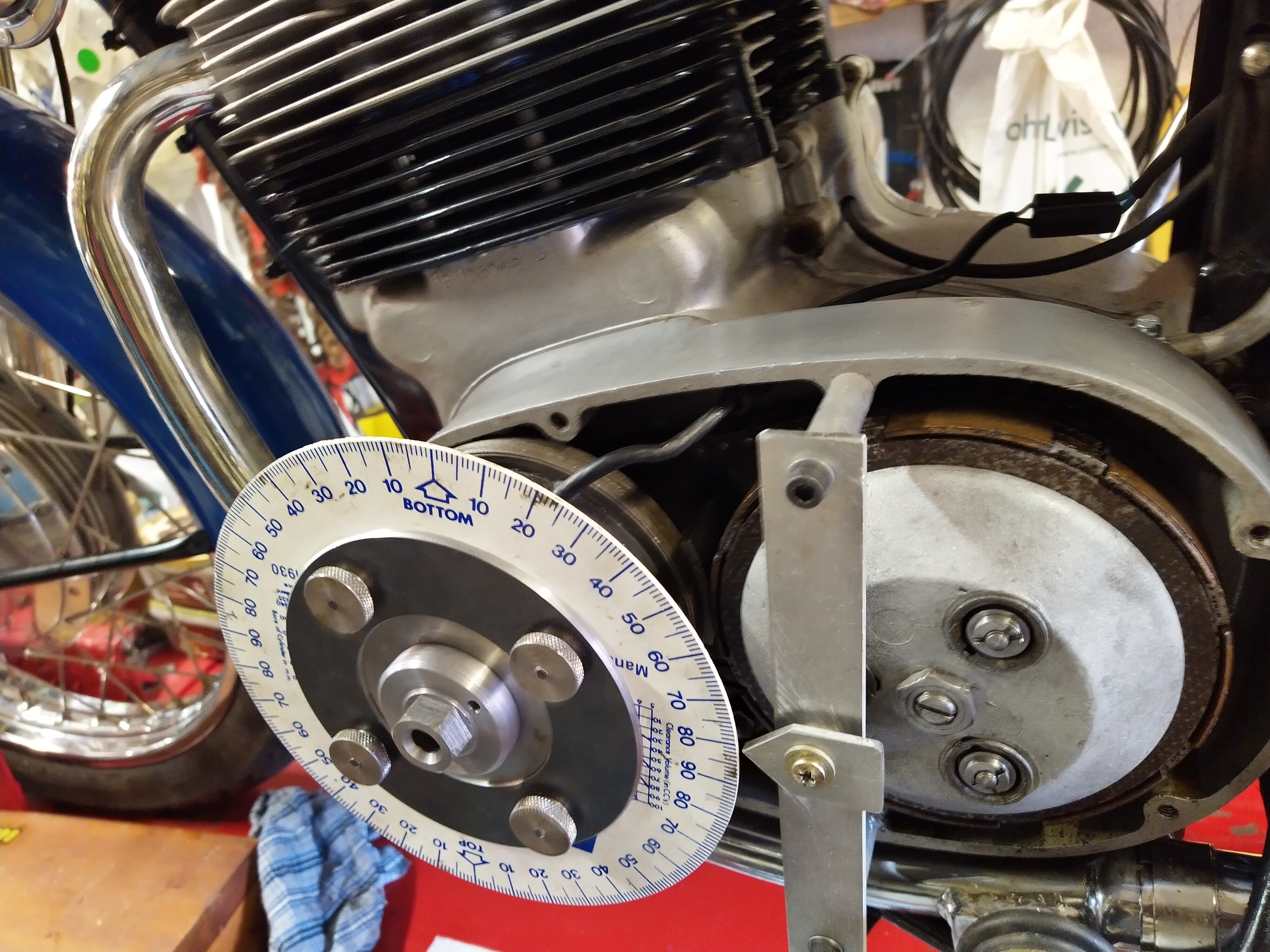
I made an expanding mandrel that fits tightly into the crankshaft starter ratchet. An 8mm stud tightened things and provided the central mount for a timing disc. I thought removing the ratchet rediculous for a timing check. Photo attached.
Obviously you have to remove the outboard starter sprocket and starter chain.
Set the timing disc zero position with a piston stop.
I find the Pazon can then be timed statically.
And check the timing and advance curve with a strobe. The disc doesn't move if you keep the throttle action gentle.
Peter
- Log in to post comments
Timing disc on Electra
Ian,
Photo of timing disc on expanded mandrel with pointer.
With electronic ignition set correctly, you can forget about timing going "off" as with points. No need for inaccurate approximate paint blobs on the rotor.
Peter
- Log in to post comments
Timing
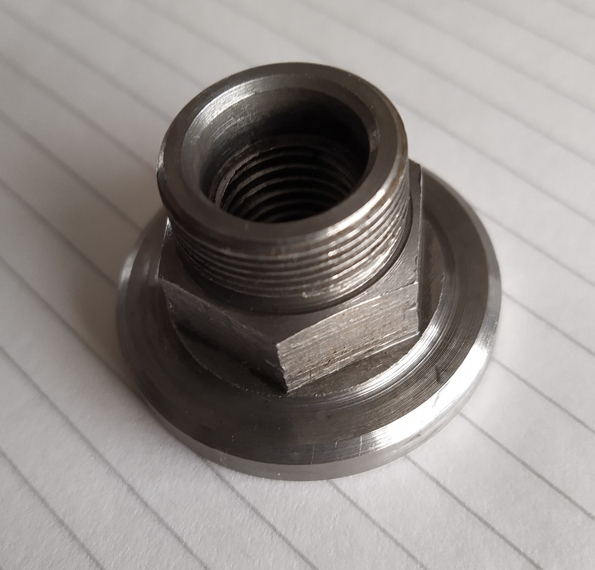
Would it be possible to make a nut like the one in my first photo. It has an external thread that the timing disc screws on to, second photo.
A large diameter timing disc will give better accuracy than small diameter disc. My disc is "adjustable" so I can use a substantial fixed pointer rather than a bit of bent wire.
This may sound like a lot of work for what may be a one-off setting. My engine is a mixture of new, old and original parts, as they bed it may, or may not, alter the timing. I will check at some point. Wear and tear might alter things, especially in a well used engine.
One of the first jobs I did on the Navigator was fit a Boyer system. I thought this is going to be a messy business, running the engine with the chain case cover off, oil everywhere. needn't have worried didn't seem to fling oil at all.
- Log in to post comments
Timing the Electra
John, that looks a very professional set of tooling for timing a Navigator. Greatly admire the thoroughnesss.
Your Navigator has a stud in the crankshaft end, thick washer and nyloc 1/2in BSF nut. Some threads exposed on the stud if you are lucky, which can be used to secure a timing disc that clears the alternator stator.
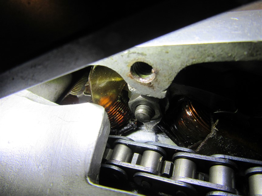
The Electra does not have a stud. The ratchet takes the place of the thick washer. A bolt with a very thin head screws into the crankshaft end and must be secured by a tab washer of unusual shape. Inside the ratchet. Very hard to bend the tab onto the hexagon side. See the left hand detail of the first photo I posted. One tab is folded up, the other at 30 degrees is left unfolded.
So unfortunately no chance to use a nut as you have made.
I looked for a way of securing a full size disc without disturbing the starter ratchet and particularly the bolt and tab washer.
Peter
- Log in to post comments
Timing disc on crank shaft
Peter, just been looking at the GA of the Electra starter. (Found it on an old thread on this forum).
I think it possible to attach a timing disc to the end of the crank shaft. The way it might work would to be make an extended bolt, the one that hold the ratchet centre. This would need a hole through the sprocket shaft. The extend bolt could have either male of female thread for an adaptor to hold a timing disc.
I roughly scaled the GA on the screen so the thread in the end of the crank was 1/2" diameter. Crude, but made me think it could work.
I guess that all this is irrelevant, the OP wants to be able to set the ignition timing without disturbing the primary chain case cover. I think the problems of thrashing chains, oil spraying everywhere and working both sides of the bike have been over stated.
However the job of is done, one point that has not been mentioned is ensuring the timing disc, or whatever carries the timing marks, runs as true as possible. Those cheap, readily available plastic discs can be rather inaccurate. The hole in the middle and the rings around it for resizing are frequently eccentric to the graduations. The error is often magnified by poor mounting Typically, these discs are about 160 - 180mm diameter, 1 - 1.5mm graduation spacing, consider the error that a 1mm run out will cause.
- Log in to post comments
I take the points made....
... but am trying to avoid the mess of trying to strobe a very inaccessible pointer / rotor relationship whilst being sprayed with oil....
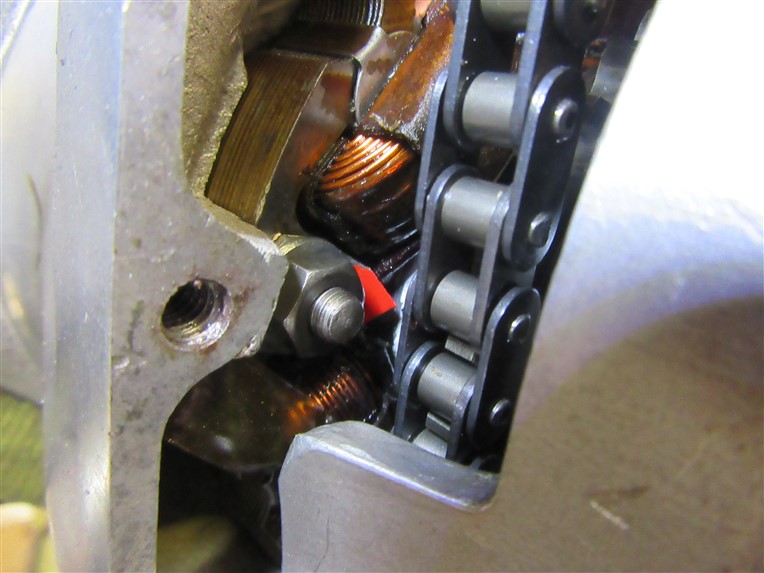
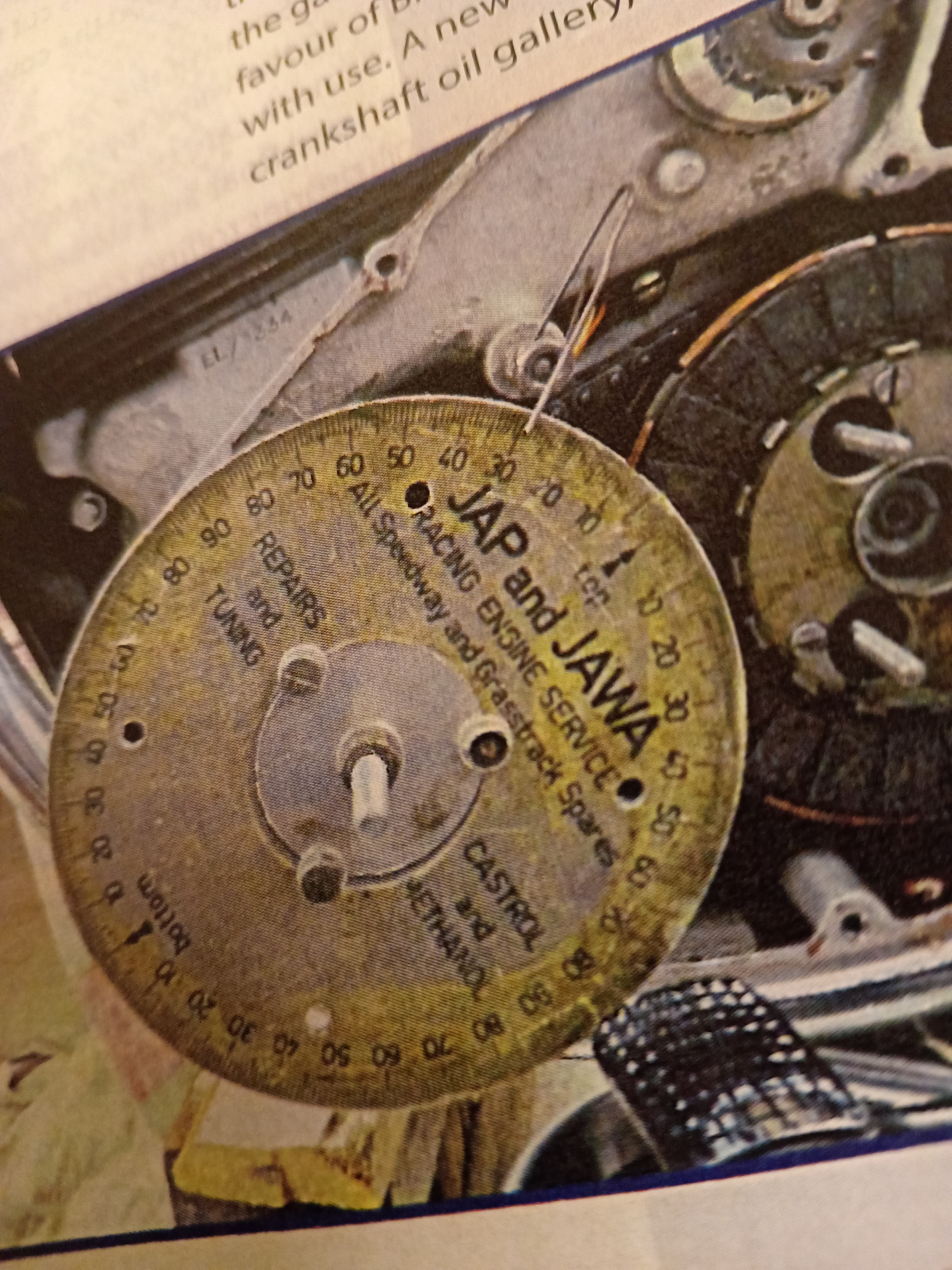
This shows the pointer i have made (since painted red for visibility) attached to a stator stud and the rotor. I have marked this at TDC and 30 degrees BTDC but those marks aren't shown. Of course I set those marks using the piston stop / degree disc as described so am confident they are correct. I think I have described elsewhere the use of a counterbored and tapped spare sprag clutch bolt for this purpose.
I maintain that as long as I carefully locate the marked Boyer rotor centrally in the hole in the PCB whilst checking (using my marks) that the crank is 30 degrees BTDC then this will be as accurate as the recommended method. Of course it will have to be viewed and strobed orthogonally to avoid parallax errors.
All this is a little academic at the moment as I have lots of other stuff to do. Recommissioning? Give me strength......
- Log in to post comments
Further.
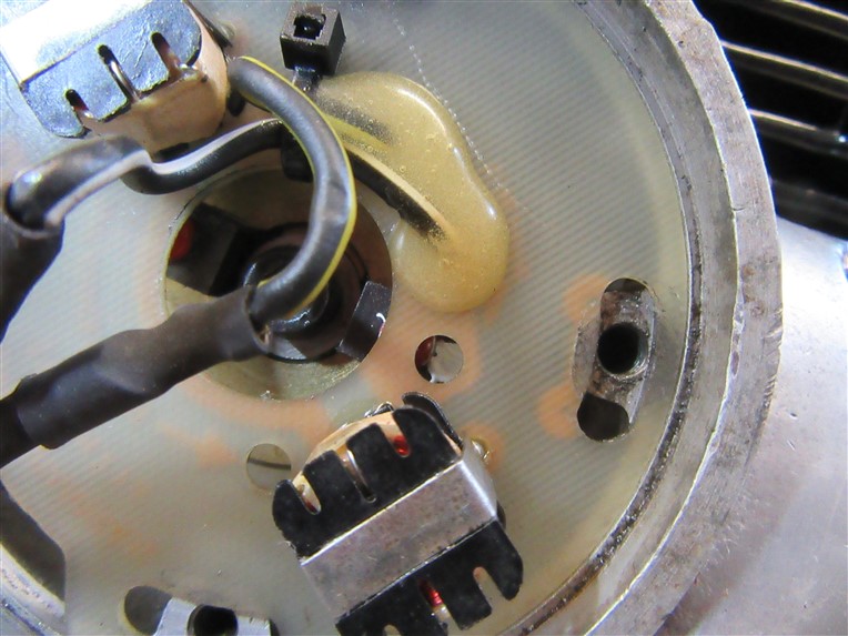
On my web site is a pointer I made from a scrap of aluminium, usable on all lightweights. this gives a fixed point. And stays on the engine. I then found TDC and (30deg) of the crank/rotor going round by 'hand' and marked the rotor. So when engine is fired up you can see the (30deg) point coming towards the fixed point with the strobe. I can't remember any issues with chains/oil flying about, or the starter sprag getting in the way.
- Log in to post comments
That's exactly...
... what I've done Al. But I still don't see why my method won't work. I accept it will only be about half the precision of measuring at the crankshaft.
Another consideration is that my medium range eyesight is very poor despite using varifocals so think this will be easier to see.
To someone used to timing an ES2 with a spoke and filed notches this is all a bit high tech. And I haven't used my strobe for at least 30 years. Will it still work? Who knows.....
A couple of pictures:
- Log in to post comments
Your Boyer
Ian,
If your photos are of a Boyer device, and it has been made for Lightweights.
It has been installed previously or is second hand.
Boyer and Pazon pcb's are often a bit tight. The outside diameter needs a mild shave with a file to get it to fit in the recess and rotate for adjustment with reasonable force.
The slot features are just set on too small a radius. So you have to take a needle file to the outer slot face. Look at the bottom of your central picture and you will see someone has been at the pcb slot with a file.
But not the slot in the lower picture?
All very academic I hear you say. Yes, but you are not dealing with a big single here. And when you come to set the timing the circumference of the pcb represents 720 degrees of crank rotation. And the circumference is about 200mm. So one degree on the crank, third of a mm?
Accuracy is king for good running as others have said.
Peter
- Log in to post comments
I don't think your blob…
I don't think your blob appearing in the hole is accurate enough. My 250 had to be accurate to less than two degrees, just like the book says.
Scribe a line in the white paint, lining up with a notch or line in the plastic baseplate at 30 degrees BTDC, having turned the crankshaft forward to that position.
- Log in to post comments
Well, further thought tells me...
... that you're all (mostly) right - particularly Stan's point. There's no point (pun intended) trying to line up with the PCB as it must be able to move to adjust. However, what I may try is making a top hat type of component out of alloy which can be secured on top of the rotor and can have 2 lines scribed on it 15 degrees apart (TDC and 30 degrees BTDC). I can then use a pointer secured on one of the pillar bolts to line up with it.
I like the idea of strobing from the timing side as that's the side where any adjustment will be made and saves hopping from side to side of the bike.
How to people verify the 5,000 rpm engine speed - this has always seemed very high to me for a bike sitting on its centre stand? I remember trying to do this on my Commando which was walking all over the drive, the stand of course being attached to the engine plates so not having the benefit of the isolastics.
- Log in to post comments
Sketch of top hat rotor

- Log in to post comments
You could get one of these…
You could get one of these BSA/Triumph timing discs;
eBay item number:196045834247
They seem to be available with cycle or UNF threads, they replace (temporarily) the auto advance bolt.
- Log in to post comments
Food for thought
Now that is a idea, also with a bit of forethought prior to initial rotor fitting you could find TDC and spark timing point to more accurately set the rotor and clamp it on the taper. Then if required remove your top hat and fit the PCB plate if not already fitted.
I would be tempted to use a casing screw to fit the pointer because if you had to slacken the plate to adjust you would probably disturb the pointer position.
You could make for easier and more accurate timing if the top hat was a centre for mounting a larger plastic timing disc with cutouts to access the adjuster screws. (as I've just noticed posted by Darren). I know you couldn't gain access to the screws with the engine running but would be easy when it's stopped.
I had in passing thought about it being easier to check and adjust the timing from the same side, but had not thought on your idea. As for 5,000rpm, when I was checking mine I thought of entering it in 'Strictly' the way it was dancing around.
- Log in to post comments
Thanks both.
My idea is to leave the top hat permanently in situ as it won't interfere with anything else. Material may be alloy or acetal. I agree using a casing screw (or a suitably longer one with appropriate spacers). The plan is to use the TDC and firing point markings I have already made on the alternator rotor / pointer on stator for setting my top hat.
All is a bit hypothetical at the moment as lots of other things to do......
- Log in to post comments
I've just been looking...
... at the Boyer instructions and they mention a 10 degree camshaft advance range. I wonder why I can't time it at idle on the 5 degree camshaft position (would mean 3 scribed lines, perhaps very close together).
- Log in to post comments
"There's no point (pun…
"There's no point (pun intended) trying to line up with the PCB as it must be able to move to adjust."
Yes, that was quite a stupid thing for me to suggest.
- Log in to post comments
The advance/retard range…
The advance/retard range varies between individual ignition boxes.
The fully advanced timing has to be correct and you don't know how far your Boyer or Pazon is going to advance until you have a strobe shining on the marks and rev it until it stops advancing (or stops advancing significantly). That is usually around 5,000 rpm.
There is nothing wrong with revving to 5,000 rpm.
It's noisy- so what!
It moves across the floor on the stand- put the stand on a rubber mat or a cut out bit of old tyre.
- Log in to post comments
Your neighbours...
... may be less sensitive than mine!
- Log in to post comments
The only reason to set your…
The only reason to set your timing according to the instructions is your bike might run properly.
There are loads of reasons not to do any job, if we set our mind to it.
- Log in to post comments
In case anyone did not see…
In case anyone did not see Peter's response (The way the forum threads get updated means it appeared in the middle of the thread). Slightly modified, I hope you don't mind.
This is a very important point. If you use the disk mounted on the camshaft end rather than the crankshaft end, then one rotation of the timing disks represents 720 degrees of crank rotation.
As you are trying to set the timing 'spot on' then the inevitable slight jitter you will get even with electronic ignition means you are aiming for a middle range, so maybe +/- 1 degree.
Using the camshaft end means this becomes +/- 2 degrees.
Also remember, when you come to set the timing, The PCB circumference is about 200mm. So one degree on the crank is about third of a mm rotation on the PCB.
- Log in to post comments
Yes Tony,
I did in fact allude to that point. However, a lack of precision here will in my opinion be offset by the much improved visibility as well as the ability to adjust on the fly. And when I look at some of the wobbly wire pointers that some advocate for setting TDC I can't imagine that they are very precise. I myself use an offcut of 1mm alloy sheet cut to a point which allows me to get within a degree. It's interesting that John Hudson suggested using a length of pushrod or similar through the plug hole and held in one's fingers(!) to establish TDC rather than a dedicated piston stop (p32 of the lightweight twin compendium).
I sometimes think that people are searching for a level of precision and accuracy that could never have been achieved with the original equipment. And I see nothing wrong with exploring alternative solutions.
Anyway I'm pleased that my thoughts have engendered a reasonable discussion.
Oh, just noticed Peter's point re PCB diameter - this rotates freely in the housing and with the screws backed off a turn it's easy to rotate it in very small increments.
- Log in to post comments
Someone with skill can feel…
Someone with skill can feel for TDC with a stick and also find where the points open, with fag paper or 1 &1/2 thou feeler blade, within a crankshaft degree. Lots of people can't.
A strobe is still better, because points timing doesn't always behave itself as you rev up. For example, any looseness of the moving contact on its pillar can send the timing all over the place at higher rpm.
- Log in to post comments
With a stroke of 56mm?
Hi Michael,
"Someone with skill can feel for TDC with a stick and also find where the points open, with fag paper or 1 &1/2 thou feeler blade, within a crankshaft degree. Lots of people can't."
On a lightweight the plug is at 45 degrees to the bore. Not so easy to put a stick down and feel for piston movement as you turn the crank. Also the stroke on Ian's Electra is only 58mm. So at 30 degrees the piston has descended only 3.75 mm. Measure by feel and fag packet? Not on a lightweight with any sort of accuracy. Plus or minus one degree at 30 degrees btdc is plus or minus 0.25mm on piston movement. Not a chance of 'feeling' this.
Your comment above only applies to larger strokes and preferably with engines where the spark plug is more vertical than 45 degrees.
You never had a Norton lightweight I'll guess.
Peter
- Log in to post comments
With a stroke of 56mm?
Michael below is correct.
At 30 degrees btdc the piston will be 4.65mm lower than tdc.
I forgot the conrod cants out and drops the piston a further 0.9mm.
Peter
- Log in to post comments
I get 4.65 mm. http://www…
I get 4.65 mm. http://www.torqsoft.net/piston-position.html
I did own the lead balloon that was the Norton Jubilee. Like everyone back then I timed it with a degree disc and something thin between the points. Of course it worked, but it required a bit of sensitivity!
You've cast my memory back to setting one side advanced and one retarded, because the second set of points made the auto advance inaccessible. I had forgotten that!
Some obsessives used a battery and bulb. That was easier, but not significantly more accurate.
A skilled fitter (probably not me these days and not you, by what you say) can find TDC accurately enough with a stick. You feel for what seems like a period of crank rotation around TDC where the piston doesn't move and use judgement to stop in the middle of that. Of course if a degree wheel is attached anyway, it's only sensible to use that and a piston stop to find TDC.
Nobody said anyone would set the timing on a Lightweight with a stick. Some sort of degree marks are the only sensible way.
- Log in to post comments


If you can accurately mark where the magnet or rotor is at 30 degrees BTDC (is that correct for an Electra?), then maybe your system could work.
Oil from chains isn't the biggest problem in the world though, and the alternator rotor is bigger than the trigger rotor and turns at engine speed, so timing to a mark on it will be much more accurate.