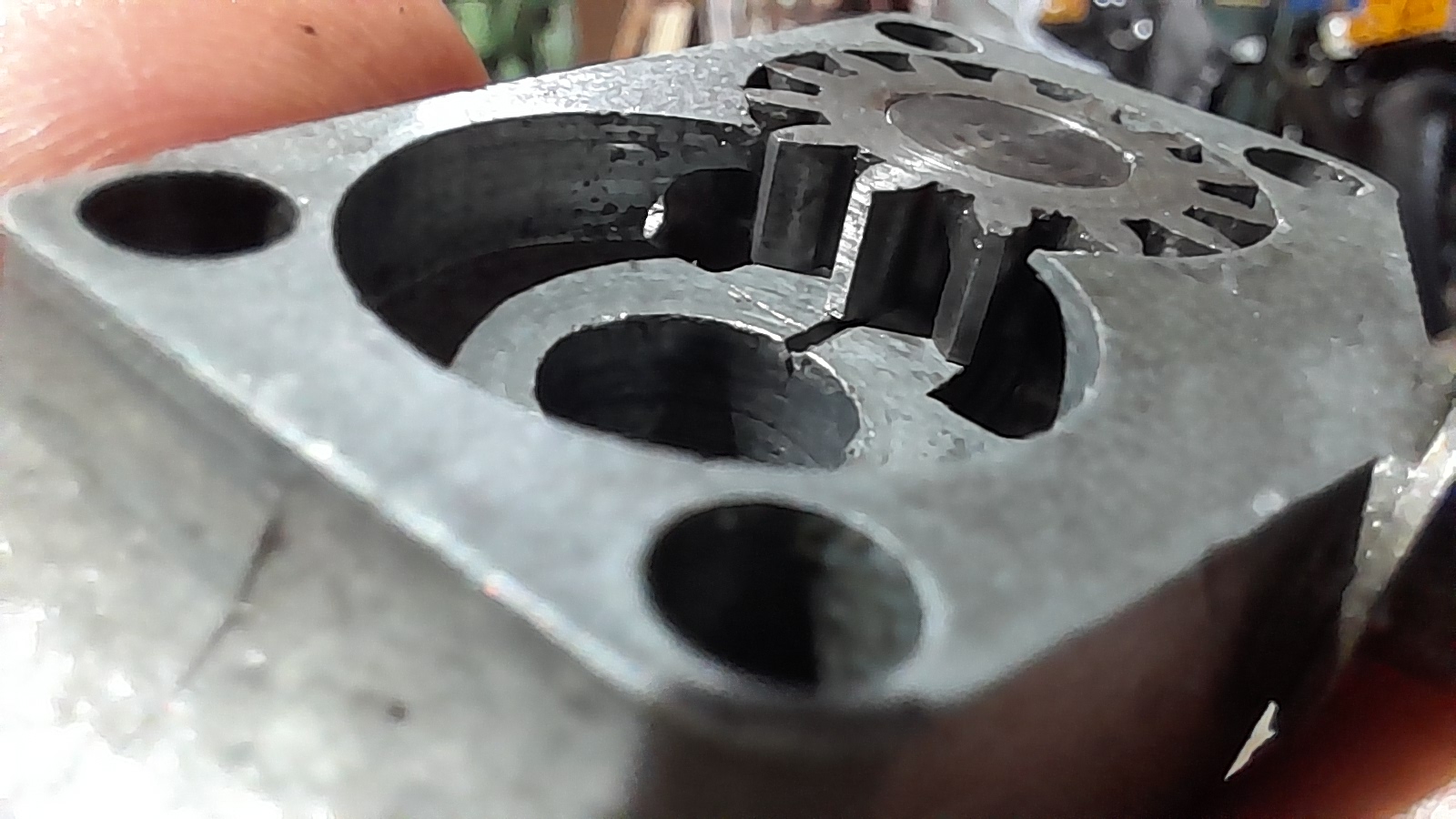
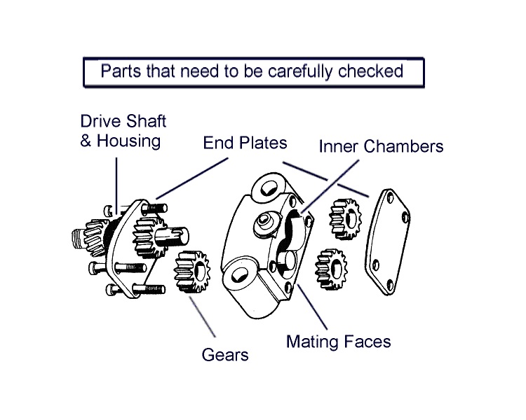
So, here's an interesting one. It is probably my insecurity, fed by inexperience, but 'when in doubt, don't cross the road' as we say here in the Netherlands. We'll not like that, we do it in Dutch: 'Bij twijfel niet oversteken.'
After reading how to check and revise an oil pump, I've decided to check the one on the engine bottom end that I have acquired recently for my project: The Surrogate Manx (link for anyone interested)
I've checked how low the gears were compared to the housing, which was 0,03 mm at the underside and 0,04 mm at the upper side of the pump. Which seems fine to me.
At least there is clearance, which I didn't expect when turning by hand. It was hard to turn with a small spot of free turning, then a build-up towards a very hard to turn spot.
It's one of the non-driven gears. Well, both, but one is worse than the other. When trying to rotate them, there's the same bit of free play and then a part that's nearly impossible to turn with my fingernail. It's like the axle is distorted, but with a short, stubby thing like that, it seems impossible. Other thing could be one of the gears being eccentric. Which is an disturbing idea, because, who sells those?
I took the gears out with a pair of circlip pliers and took care keep them the same orientation. I've slightly polished them with wet-and-dry and a bit of oil, doing figure eights and rotating them 45 degrees for four times.
To be honest, I don't think it did much. They can be rotated by hand now, but I think that's more to do with the oil used on assembly. Still, they have these strange binding spots. Should I polish the teeth (risking pressure loss) or leave them and let them rub metal against metal to lap them in?
When completely assembled, the pump 'plops' nicely and can now be rotated by hand with a friction that's not as disturbing as it used to be, but it's far from smooth with these weird friction spots.
I would appreciate any thoughts on the matter.
Cheers,
Tim
P.s. I've tried everything, but can't seem to get the text separated in alineas. Sorry about the 'word blur'.

To check the mesh of the…
- Log in to post comments
Meshing isn't the problem, but you could be onto something
Thanks Paul, you might be onto something.
The gears 'notch' without meshing, as I took out the drive one and the one attached on the other side. It's just the two gears on the fixed axle that are both notchy.
I did find on one side (with the big gears), dat two meshing gears each had one tooth with a smooth chip in it, indicating something got crunched somewhere along the line. I still can't see the axle or the housing distorting, but it would explain a lot if that could actually be the case.
If I remove the two gears on the fixed axle and just put in the drive shaft and the gear that slide on it from the other side, there's no notching. So it's just the two gears on the fixed axle.
Regarding the damaged gears. The damage they do have now to one tooth each, is so slight, I'm actualy doubting that it would affect oil pressure much or do any damage.
I'll have a go with engineering blue. Very good tip, as I completely forgot I had the stuff. It might give me an insight in where the gears are rubbing in the housing. And if all is well again, I'll lap the bronze plate. The iron one has some marks, but you can't feel them, so I'll leave that side alone.
Cheers,
Tim
- Log in to post comments
Tight spots are usually…
Tight spots are usually caused by embedded debris in the teeth of the gears, go over them with a magnifying glass and pick it all out. Close the side clearances up to zero, use a depth micrometer to measure the depth of the gear recess and compare it to the width of the gears themselves (measured with a micrometer) Often this is in the region of 3 to 5 thou. close this up to zero by lapping the pump body, you will have to remove the feed bush that is pressed into the pump body to allow you to lap it. The singles have the feed side of the pump next to the pump drive gear so to lap the feed side cover you will have to remove the shaft etc. You can lap the brass plate to remove wear but as it is on the scavenge side it is not really so important. The pump should be stiff to turn when assembled but frees off a bit when oil is introduced, You can 'run in' the pump by holding it submerged in oil and using a battery drill and suitable socket to turn the pump.
- Log in to post comments
It's that one gear...
I've polished the brass plate just for the sake of it, and polished the flat sides of the gears, just to feel how it would turn after that, before lapping the housing.
I'm glad I did, as things turned a lot smoother. Maybe the edges of the teeth were a bit burred, and I suspect they might have been, as the gears showed signs of lapping and felt extremely sharp.
But, there's always a but... when tightening the upper without putting the lower (scavenger) gears in, things went from smooth to tighter to not being able to rotate again. Which is caused by the one gear that I can't lap and that's the one fixed on the axle.
I'm glad I didn't lap the housing just yet, as that would have made things worse. I tried to remove the worm wheel so I could put the axle in the lathe to very carefully polish the gear with some wet&dry folded over a piece of silver steel, but it doesn't budge. Any ideas how to dismantle it? Is it a screw fit (left? right?) or taper fit?
- Log in to post comments
You don't need to dismantle…
You don't need to dismantle it. Hold the nut in the 3 jaw chuck and support the end of the shaft with the tailstock center, just let the shaft housing rotate with the shaft, you will be able to dress one side of the feed gear. To dismantle, hold the worm gear with copper soft jaws in the vice, undo the nut and using a puller, draw the worm gear off the shaft. Remove woodruff key and see if the shaft will remove from the housing. If the shaft has suffered you might have to remove some burrs with a fine file.
- Log in to post comments
Assembly
When replacing the 4 bolts through the end plates there is a trick of the trade that sometimes helps with tight pump gears.
First: check each bolt to ensure it has a straight shaft. Any that are bent will not allow a good re-assembly.
Second: Replace all the bolts and tighten until roughly finger tight. Next hold the body of the pump while gently rotating the drive shaft a couple of turns. Then tighten each bolt a quarter turn followed by a few more shaft turns. Keep doing this until the bolts are all tightened enough.
Third: Wrap the drive gear end thread with tape and place in the chuck of an electric drill. Either a pillar or hand-drill.
Fourth: Get a tin or pot or bowl that is large enough for the pump to fit inside. Fill this container with enough oil to cover the pump. I use old engine oil that has been through a filter. Clamp, wedge or hold the pump body so that it cannot turn and then switch the drill on to slow speed.
It does not matter which direction the pump gears turn.
After a couple of minutes stop the drill and check the pump. See how well it turns. Give the pump some more time being turned by the drill and after check the bolts are still tight. If you can change the direction the drill turns do this and then give the pump more bedding-in time.
When I refurbish oil pumps, I generally run them in the oil bath for 15 to 20 minutes varying the drill speeds to simulate a bike accelerating through its gears.
Finally, if debris has gone through the gears and chipped some it may also have twisted some of the teeth and scored the chambers. Check both very carefully.
Resurfacing the end plate by first rubbing on 300 wet & dry laid on a flat surface. Then finish by using 600 wet & dry paper.

- Log in to post comments
Done
It's done! The worm gear proved easier to remove than expected, as I found an old puller with rounded jaws that almost completely made contact with the gear. The real challenge was the woodruff key. I couldn't get a grip with (grip)pliers, but a flat screwdriver, tiny hammer and as much care as I could, I could lift the thing out without damaging the axle. It was extremely tight. Lapping the fixed gear took some thinking, as it turned out that the teeth were perfect in thickness, it was the central part near the axle on the upper side that was to thick. I wondered why the gear wasn't flat for a while, but decided it was better to focus on a solution. I originally planned to fold a piece of wet&dry around some square tool steel. However, this would dress the axle too. So I opted for a steel ruler. With the axle with gear in the lathe, I bent the ruler and carefully held the oiled wet&dry against the gear, keeping it at a small angle as not to remove any material from the teeth part, just focusing on the center part near the axle. I know, it's all a bit terrifying for the proper engineers who are reading this, but it did the trick. To set your minds at ease: I did use a micrometer to keep an eye on things. Anyway, the oil pump is now tight , but can be turned by hand, pumping round a comforting amount of oil. Thanks again all, for your input. Cheers, Tim
- Log in to post comments


To check the mesh of the gears with any degree of accuracy they will have to be coated with engineers blue or a "Sharpie" marker pen which will highlight the raised areas of each tooth as and when they are meshed together.
One thing is for sure the bronze back plate needs to be lapped so as to remove the wear caused by the two gears.
The notchyness could well have been caused by foreign bodies circulating around the system in the past.